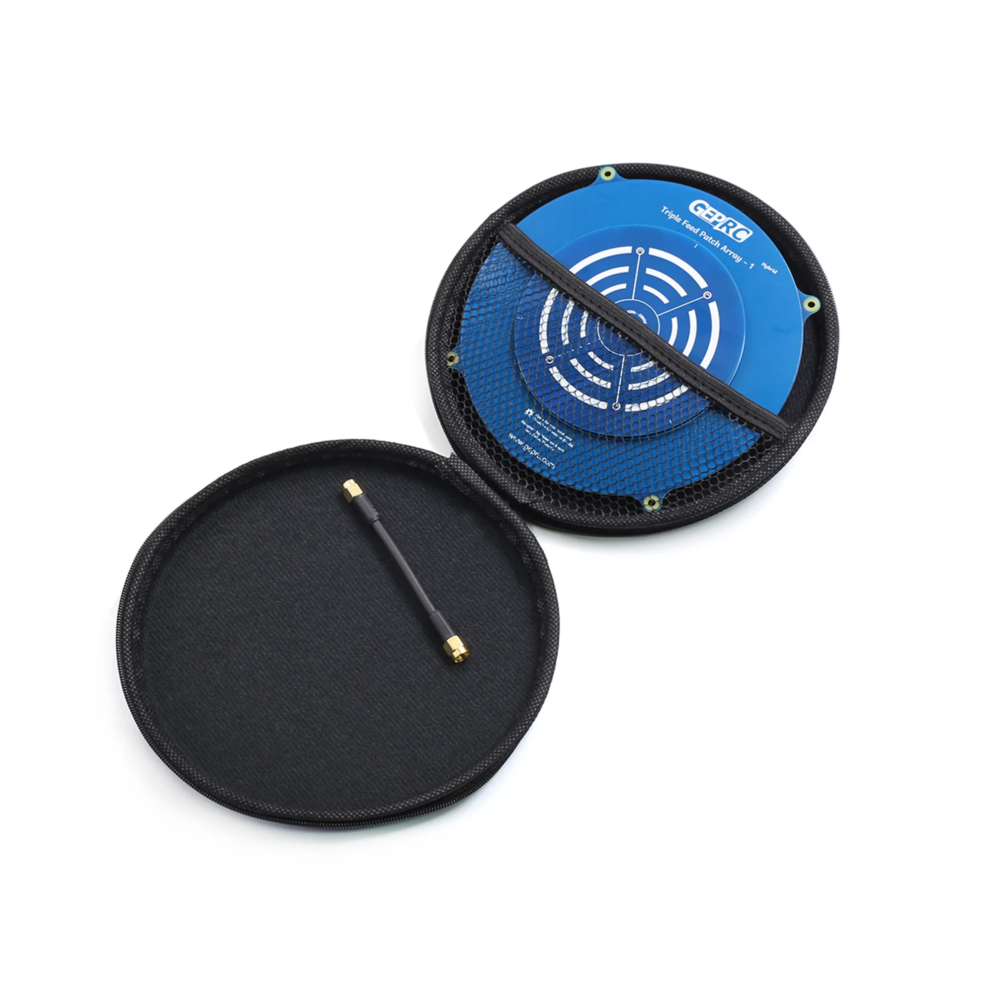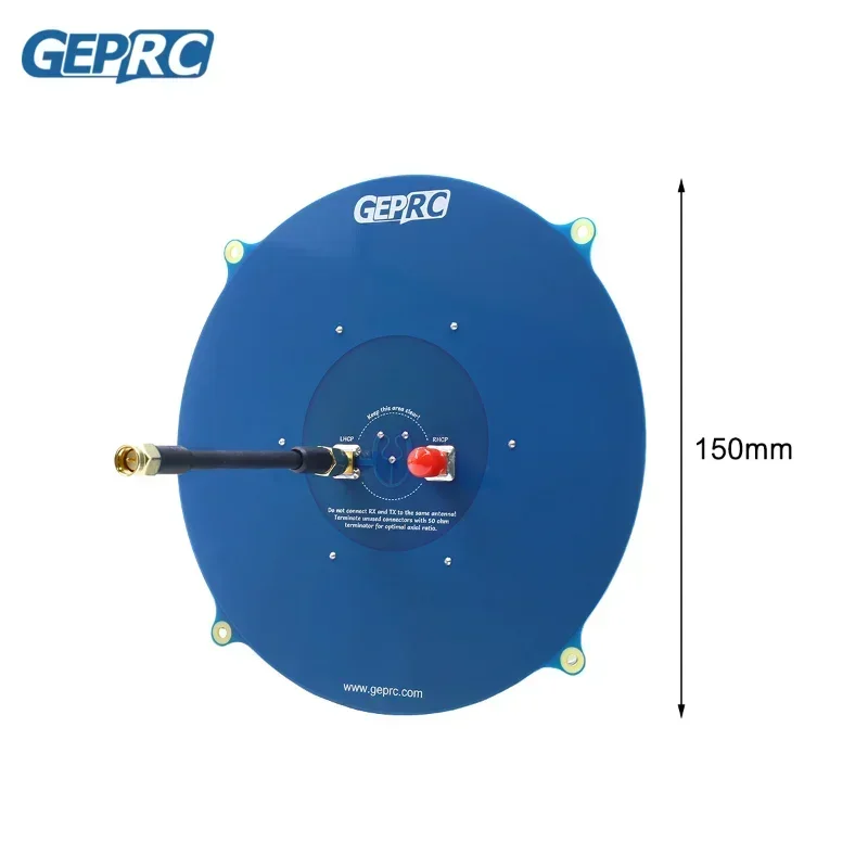
GEPRC Triple Feed Array 5.8G 14DBI Круговая поляризованная антенна FPV, совместимая с RHCP LHCP для RC Drone FPV Long Range VTX Goggle
Description
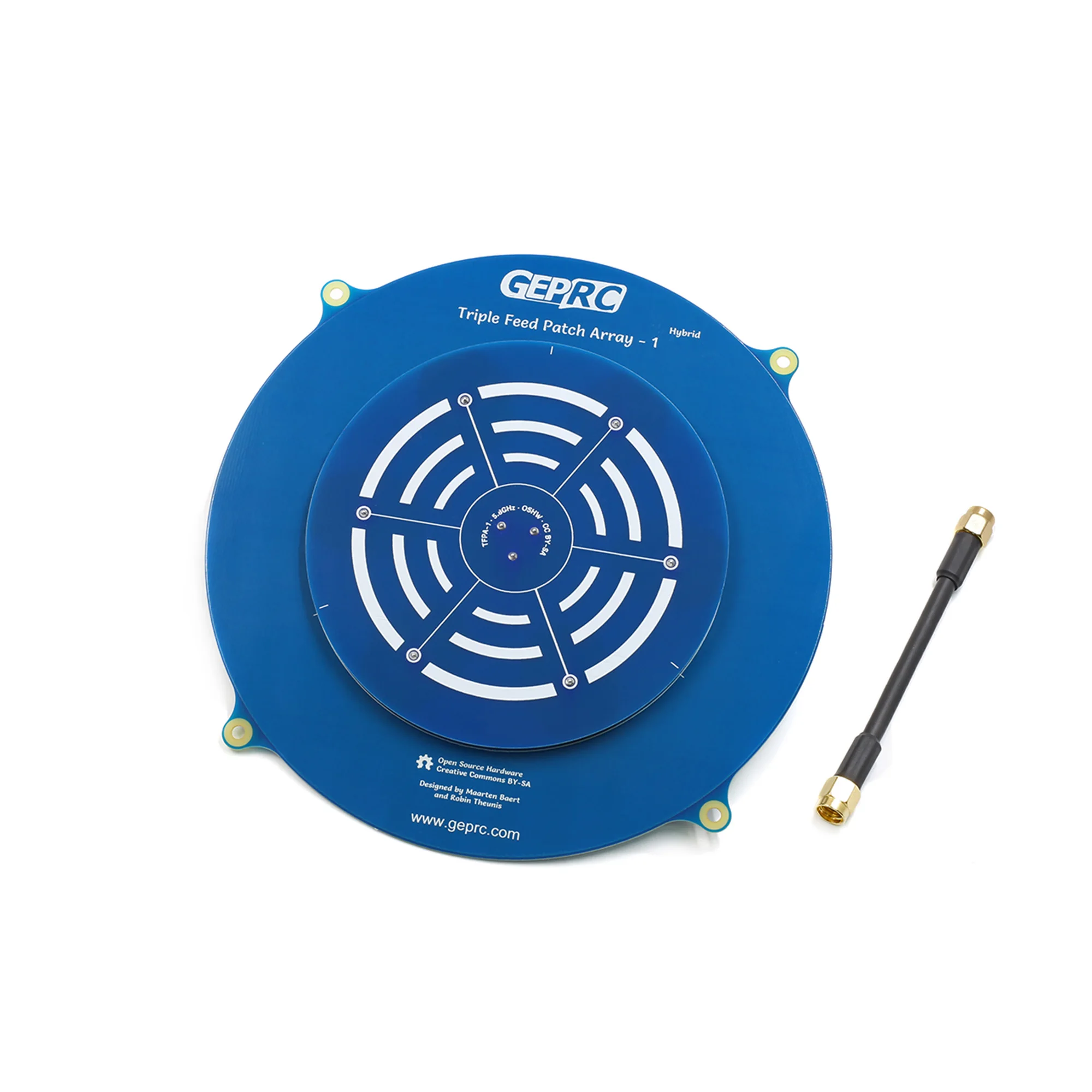
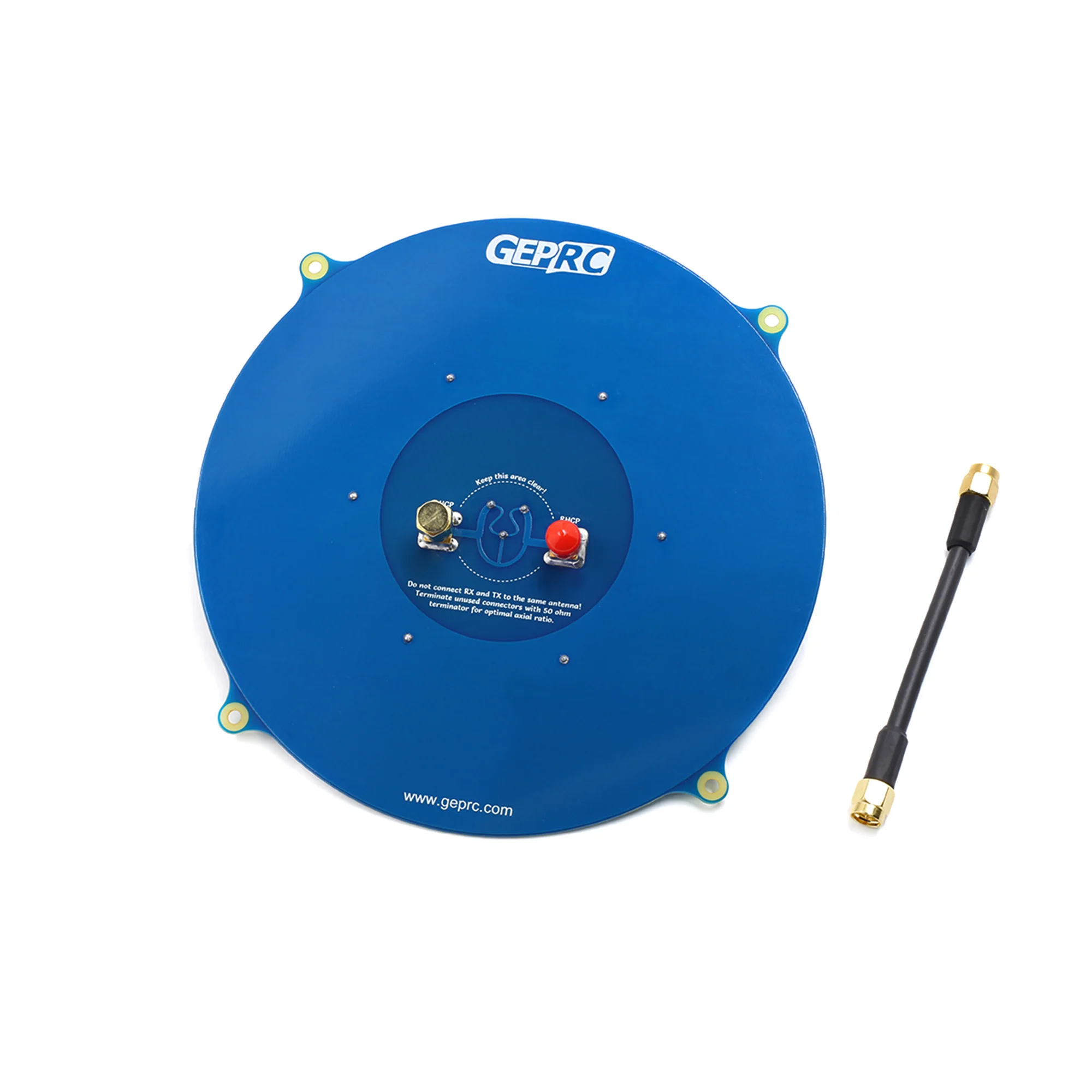
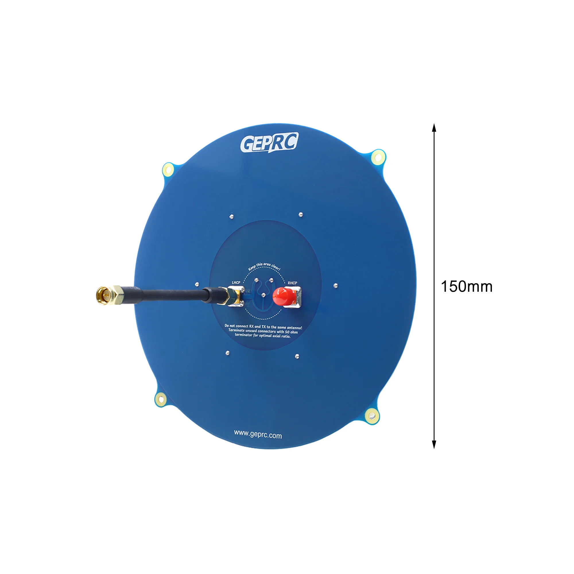
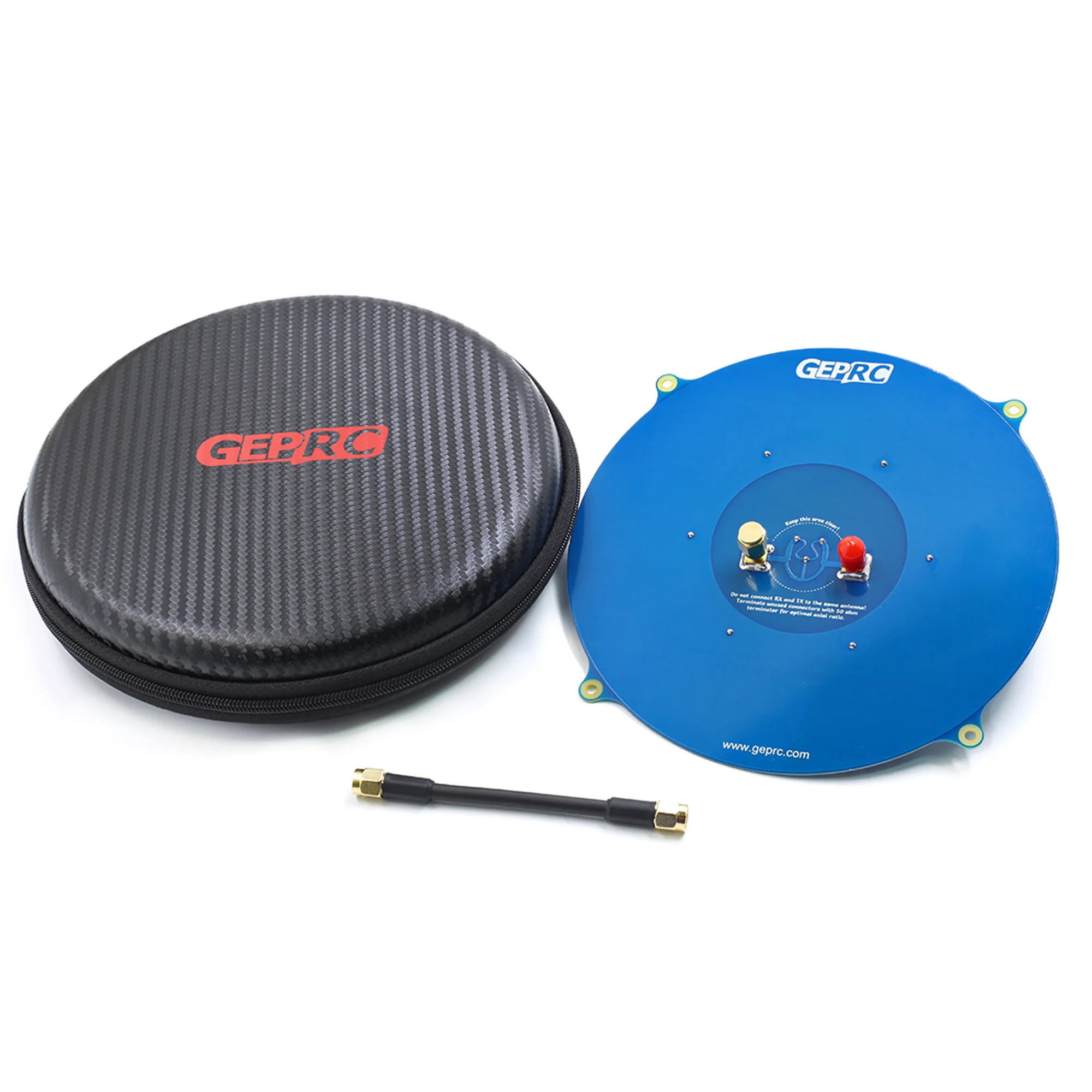
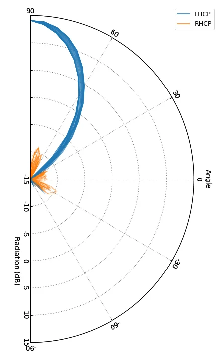
The Triple Feed Patch Array antenna is a directional circularly polarized antenna based on the original Triple Feed Patch antenna. It uses an array of seven coupled patches to achieve significantly higher gain. Since the beam width is quite narrow, this antenna is not recommended for general FPV, but it performs very well for long-range flights.
Description:
Brand name: GEPRC
Item number: Triple Feed Patch Array-1
Connector: SMA, RP-SMA (Optional)
Simulation
Measured
Comment
Center frequency
5.8 GHz
5.8 GHz ± 100 MHz
Bandwidth
660 MHz (5.47 – 6.13 GHz)
950 MHz ± 100 MHz
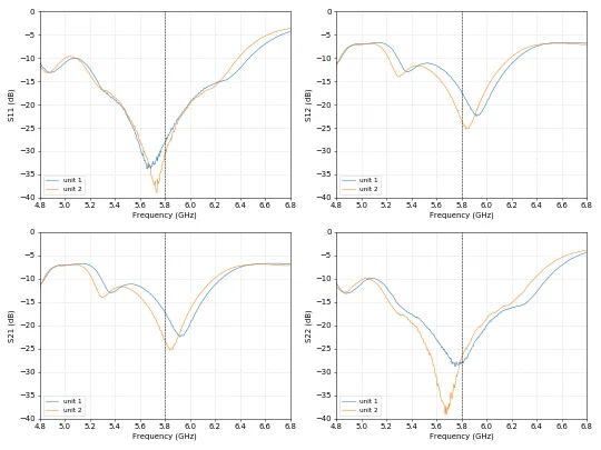
Match
S11 < -30 dB, VSWR < 1.065
S11 < -20 dB, VSWR < 1.22
Axial ratio
1.05 (0.38 dB)
1.10 (0.83 dB)
Antenna gain
14.4 dBi
14.0 dBi
Half power beamwidth
30°
Horizontal and vertical
Radiation efficiency
75%
74%
Simulation diagram:
Measured Figure:
VAN measurement:
Features:
- Good Radiation efficiency. Most FR4-based patches are very efficient because FR4 is very lossy at 5.8 GHz. In addition, most array antennas have higher losses in the feed network. This design uses coupled patches to keep the feed network simple and reduce these losses.
- Good shaft ratio, not only perpendicular to the patch but also eccentric.
- High gain, but not higher than the theoretical gain of an array with 7 elements. This is because maximizing the gain results in high side lobes and poor axial ratio.
- Very low side lobes, almost all of the energy is concentrated on the main lobe. This will increase the width of the main lobe but will increase some gain.
Specifications
| Option | Values |
|---|---|
| High-concerned chemical |
|
| Is Electric |
|
| Is it battery/power supply |
|
| Is it charger/adapter |
|
| Is Batteries Included |
|
| Material |
|
| Origin |
|
| Recommend Age |
|
| Use |
|
| Attribute | Value |
|---|---|
| High-concerned chemical | None |
| Is Electric | No Battery |
| Is it battery/power supply | N |
| Is it charger/adapter | N |
| Is Batteries Included | No |
| Material | Composite Material |
| Origin | Mainland China |
| Recommend Age | 14+y |
| Use | Vehicles & Remote Control Toys |
Product Details
The Triple Feed Patch Array antenna is a directional circularly polarized antenna based on the original Triple Feed Patch antenna. It uses an array of seven coupled patches to achieve significantly higher gain. Since the beam width is quite narrow, this antenna is not recommended for general FPV, but it performs very well for long-range flights.
Description:
Brand name: GEPRC
Item number: Triple Feed Patch Array-1
Connector: SMA, RP-SMA (Optional)
Simulation | Measured | Comment | |
Center frequency | 5.8 GHz | 5.8 GHz ± 100 MHz | |
Bandwidth | 660 MHz (5.47 – 6.13 GHz) | 950 MHz ± 100 MHz | |
Match | S11 < -30 dB, VSWR < 1.065 | S11 < -20 dB, VSWR < 1.22 | |
Axial ratio | 1.05 (0.38 dB) | 1.10 (0.83 dB) | |
Antenna gain | 14.4 dBi | 14.0 dBi | |
Half power beamwidth | 30° | 30° | Horizontal and vertical |
Radiation efficiency | 75% | 74% |
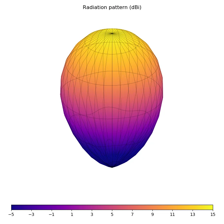
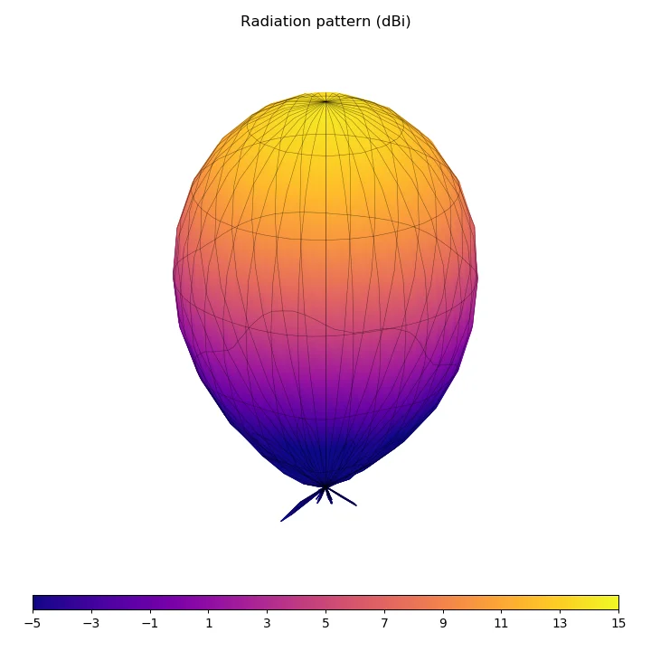
Simulation diagram:

Features:
* Good Radiation efficiency. Most FR4-based patches are very efficient because FR4 is very lossy at 5.8 GHz. In addition, most array antennas have higher losses in the feed network. This design uses coupled patches to keep the feed network simple and reduce these losses.
* Good shaft ratio, not only perpendicular to the patch but also eccentric.